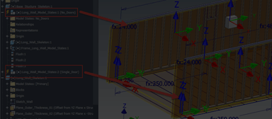

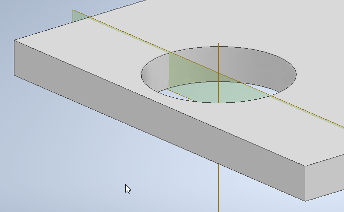
In the example below, we have a pin that is getting a plug weld into a plate. The depth of the plug weld is being driven from the top of the plate. To do this, we need to first create an offset work plane from the top of the plate down into the plate as shown:
The work plane has been renamed to “***PLUG DEPTH***” to easily find later. The next thing is to add a user defined work axis through the center of the hole to use as a feature to identify a work plane later as shown:

Now, use the work plane type “Angle to Plane Around Edge” to create a work plane that uses the axis and an origin plane to create a plane as shown:
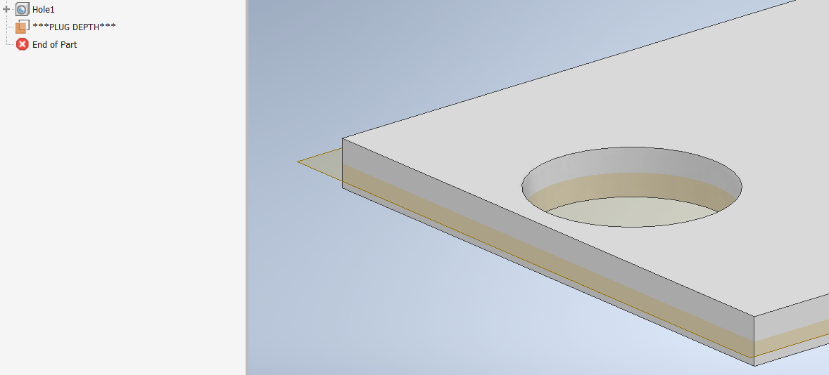
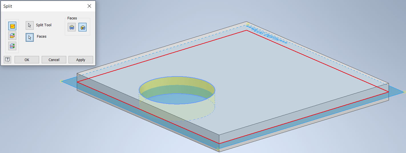
Next, use the split command to split the hole face as shown with the PLUG DEPTH work plane:
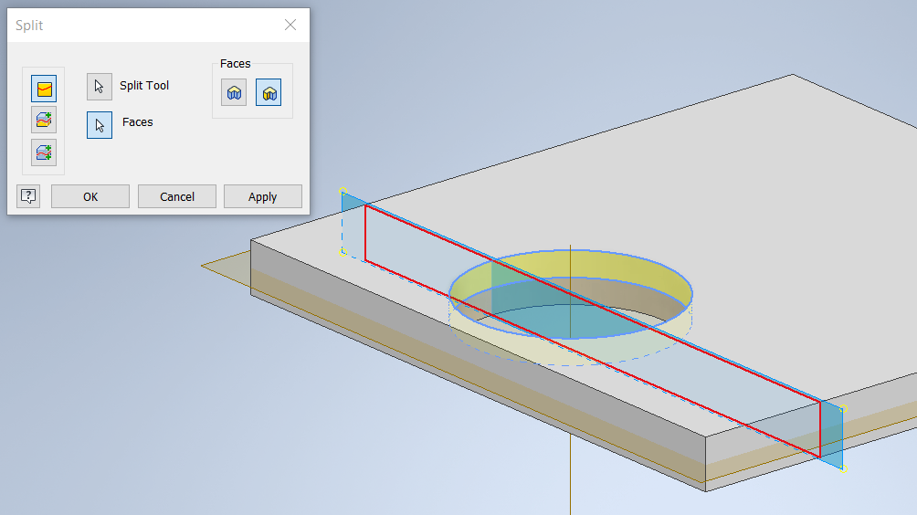
Then, use the split command again, and use the Angle to Plane work plane to split the upper faces of the hole as shown:
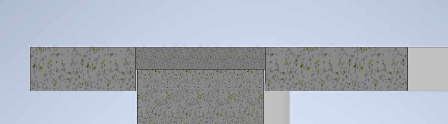
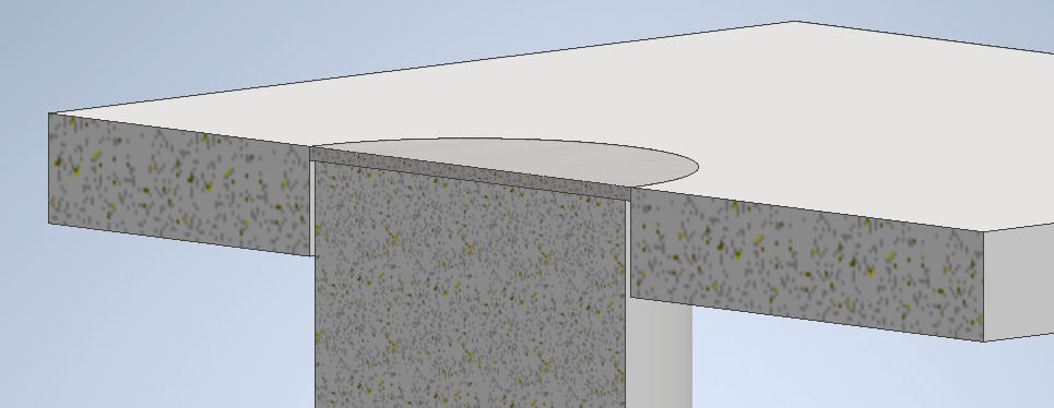
This will give a result on the faces of the hole as shown below:
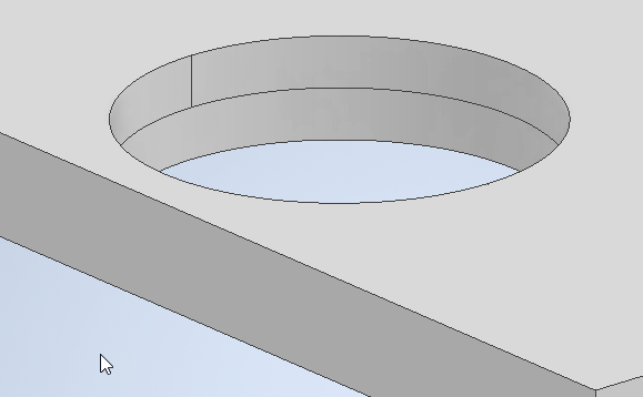
The reason the faces are split is so you can use the (2) half moon portions on the top of the hole above as surfaces to select for the groove weld command in the welding environment.
Create a new weldment and place the base plate into the assembly. Then place in the desired pin to be welded into the assembly as well. Next, constrain the center axis of the pin to the center axis of the hole. This can be done by just selecting the faces of the pin and the hole using the regular mate command as shown:
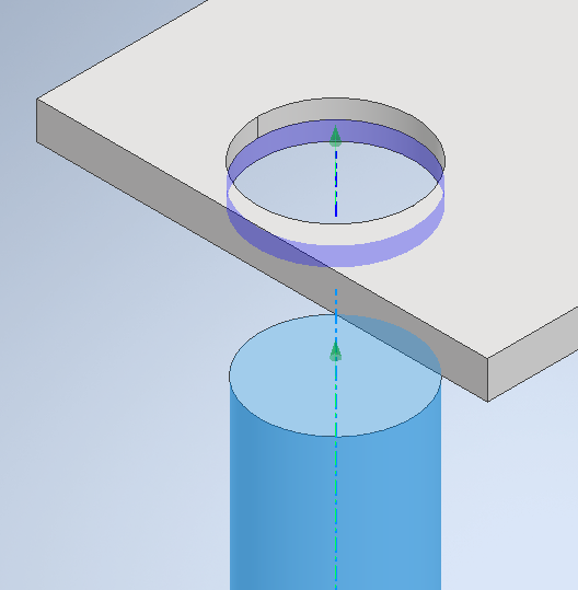
Now, constrain the top of the pin to the “***PLUG DEPTH***” work plane in the base plate. This is important because when the depth of the work plane changes so does the depth of the plug weld.
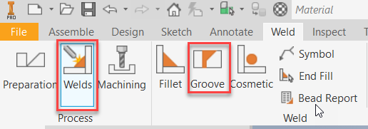
Start the welds and choose Groove weld:
Make sure to choose one half of the upper portion of the hole for Face Set 1 and the other half of the hole face as Face Set 2. It is important to choose “Full Face” checkbox for each face set as well, or the weld will now work:
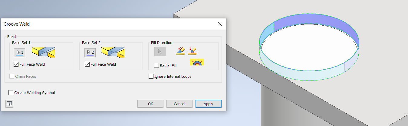
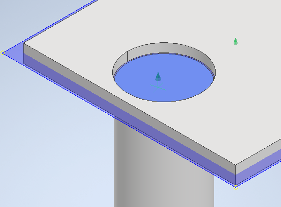
Choose OK and see the plug weld:
Changing the depth of the Plug weld work plane in the base plate will also update the pin location and plug weld depth as shown below:
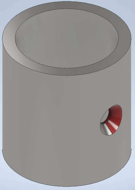
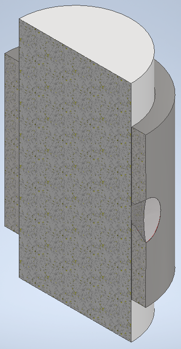
All the same concepts from above apply to cylindrical parts as well. In the example below, a countersink hole was split in half to use as groove weld faces:
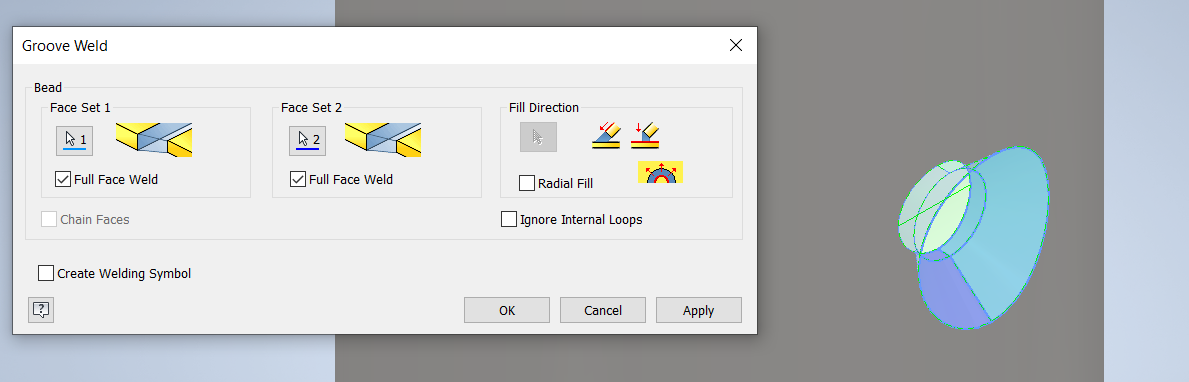
Using the red face as “Face Set 1” and the other faces as “Face Set 2” ensuring the “Full Face Weld” option is set for both face sets as shown below:
Some quick tips for today. Please let me know your questions or comments down below. Thanks for reading, happy blogging! - Brad Bland
Do you use any of these tips and tricks in your daily workflow? Feel free to brag about your success in the comments!
Like what you’ve read? Subscribe to our blog!
Feel free to share on Twitter or Facebook!