
Manipulating a 3rd Party Assembly: Part 1
To Import or Open; That is the Question
Turns out the CAD world is a big place with lots of different tools available to further our design pursuits. Some of the tools are generally very good, while other tools do an excellent job with some very specific design tasks. Unfortunately, while all these various design tools are great for rounding out the design world, many of them have very specific file formats for facilitating this unique functionality and those formats don’t always play nice together.
All designers will at some point have to work with data from different CAD packages to complete a design. In this week’s blog I’ll kick off a 3-part mini-series covering the usage, manipulation and common complications when manipulating 3rd party CAD data. The first step in the process is to determine the best way to get the data into Inventor.
I love perusing GrabCAD when looking for sample models or little trinkets for my designs, so (as usual) I went there first to find a sample model. Also, as usual, I was not disappointed. I quickly found a robust lathe model from Francisco Miguel Teixeira, found here, which I will be using as the basis for the blog series.

Rendered Image of the Lathe (Courtesy of Francisco Miguel Teixeira)
Now that we’ve got a great candidate model, the first hurdle is how to get this model into Inventor. The creator modeled this assembly in Solidworks and provided a version in the universal STEP format, so (as both formats are valid for Inventor use) we’re good there. The real question becomes what do we wish to do with this model? That answer will help to determine which method we utilize to import / open the model in Inventor. Below are some common scenarios:
- 1. Just the use the model as is. (in this example, we may be
creating a manufacturing layout model.) - 2. Import the assembly and swap out some of the components.
- 3. Import the assembly and make changes to the models.
Scenario #1 is pretty easy to accomplish. One would use Inventor’s AnyCAD technology, to just use the data as is, no modifications required. That’s a blog for another day, but you can check out this Autodesk post on it for more information on the AnyCAD functionality.
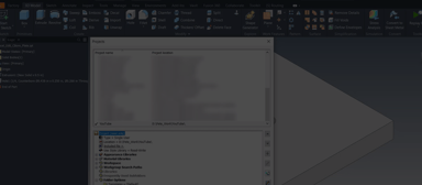
To cover scenario #2, we’ll have to convert it to Inventor format, so we can swap out components or make changes to individual components. This can be accomplished by Placing the assembly into a higher-level assembly or by trying to Open the STEP assembly. Simply choose the Convert option and make any desired adjustments. The settings I chose are shown below.
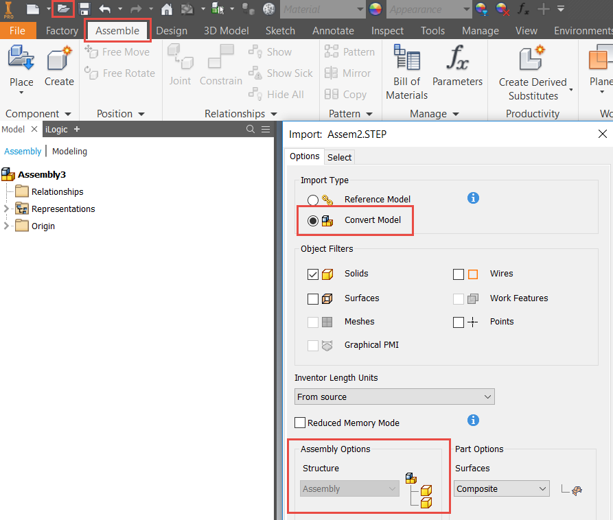
Dialog Box Settings when Opening the STEP Assembly

Resulting Imported Assembly (Note the Structure of the Model Browser)
Scenario #3 is where I spend most of my CAD life and is what I’ll be focusing on for the remainder of the blog post. We’ll often want to utilize this approach when preparing models for use in Plant 3D, Factory Design Utilities or Revit, where the assembly structure is of little use to us.
The reasons for this are often we’ll want to simplify the models or make changes to the size of a model. Instead of trying to modify several components, if the structure remains as an assembly, it is much easier if the imported assembly is converted into part file.
This will allow us to use many of the 3D Part modeling tools that are quite familiar and a not so familiar tool (for some) that we’ll discuss next week.
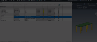
To convert this assembly file to an Inventor part file, we’ll actually need to start by creating a new Inventor part file. This is the easiest way to convert a 3rd party assembly model into a part file. Inside the new Inventor file, utilize the Import command and choose the appropriate settings. Mine are displayed below.
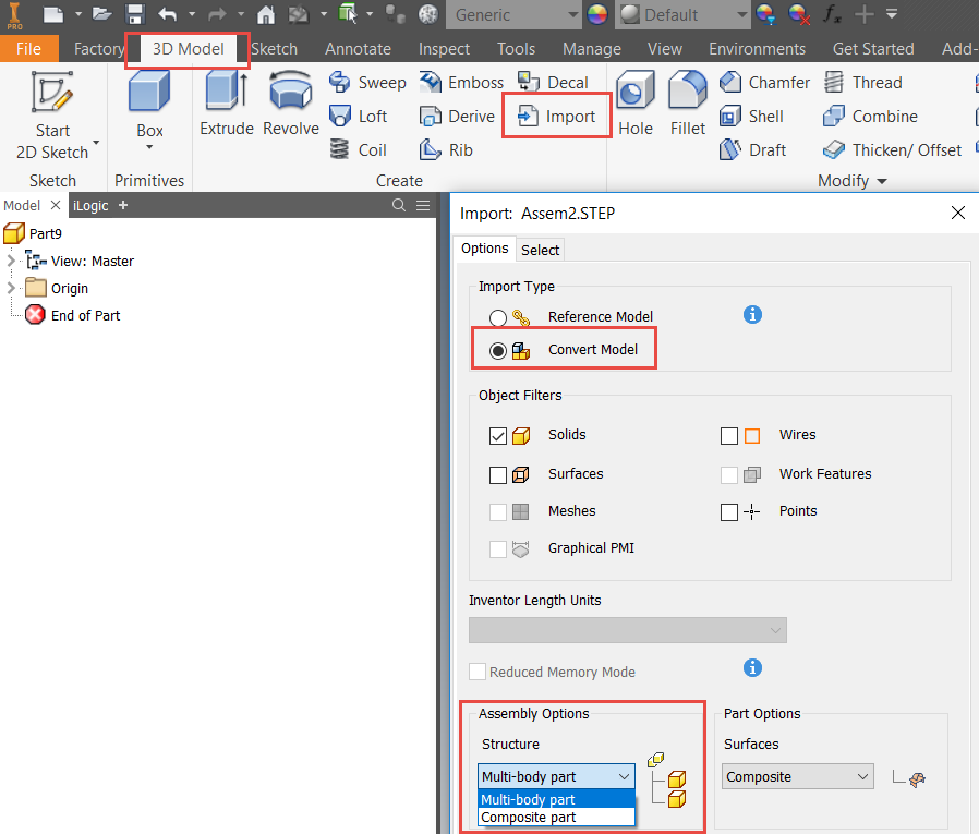
Settings for Importing and Converting the STEP Assembly into an Inventor Part File

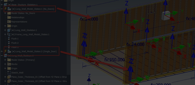
Resulting Part File with Each Assembly Component Converted to a Solid Body
This model is now ready for further simplification / modification with the ease of everything being contained into a single “dumb solid” part model. While one can utilize the Composite surface option, I don’t advise that, as those aren’t particularly useful for modification. In the next blog post, we’ll manipulate this multi-body model, by resizing the lathe bed length to handle different layout situations. As always, if you have any questions or comments, please us know below! Hope you found this useful, happy blogging and have a most blessed day! - Pete Strycharske
Do you use any of these tips and tricks in your daily workflow? Feel free to brag about your success in the comments!
Like what you’ve read? Subscribe to our blog!
Feel free to share on Twitter or Facebook!