While injection molding simulation is a common tool used by molders and toolmakers to help evaluate their mold design, it is often implemented after the plastic part design has been finalized and a tool design has been developed. This article will highlight how proactively using injection molding simulation (Moldflow®) can help yield information that allows for better plastic part design and help drive mold decisions prior to developing the mold design.
Injection molding simulation has become a powerful tool to help optimize plastic part design and mold construction. However, it is often a tool that is delegated to molders and toolmakers to validate their proposed design to their customer and get approval to move forward with the tool construction. However, by delaying the use of simulation in the design process both part designers and molders/toolmakers limit the opportunity to allow for using data to drive design decisions and yield a higher quality part. This article will highlight some key design decisions that can be made regarding the plastic part and mold designs before a mold design has been fully developed.
Establishing a Nominal Wall
One of the most important decisions that a designer can make is to properly select the nominal wall for their plastic part design. The nominal wall will help drive many decisions regarding the overall part dimensions, required auxiliary features such as ribs, bosses and snap fits, gate location, and material selection. While this decision is ultimately driven by the required performance criteria for the plastic part, it needs to be remembered that the part must also be manufacturable. Since injection molding is a pressure-driven flow process, the designer must remember that as the nominal wall is reduced the required injection pressure to manufacture the part will increase. If the required pressure becomes too high, then the nominal wall will need to be increased, or multiple gates may be required to fill the mold. Utilizing injection molding simulation can help a product designer better select that nominal wall by ensuring the pressure to fill the part remains below a certain pressure threshold. This will allow the part to be manufacturable for the molder with a wider processing window, Figure 1.
Once the nominal wall thickness of the part has been established, the designer should avoid any unnecessary wall thickness variation in the part to avoid different cooling rates and potential part warpage during manufacturing. Additionally, the designer should drive their decisions regarding rib thickness and boss placement based off the nominal wall selected.
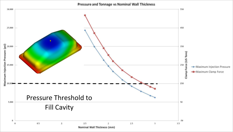
Figure 1: Injection molding simulation can help determine what is a feasible nominal wall thickness of a part for the desired material and design of a product based on maintaining an attainable injection pressure to fill the mold.
Evaluating Design Risk of Auxiliary Features.
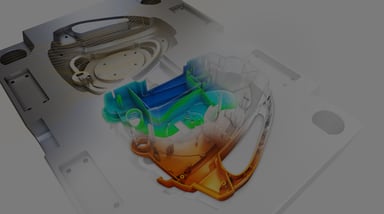
Once the nominal wall thickness and overall appearance of the part have been established, the designer often turns their focus to adding in assembly features such as bosses, ribs, and snap fits. A quick review of best plastic part design reveals that the base features are often dictated by a nominal wall section of the part. However, the integration of these design features introduce inherent wall thickness variability into the part that could increase the risk of manufacturing issues such as sink or short shots, and design issues like dimensional stability. Figure 2 shows a mouse that has three bosses used for assembly. By quickly running a series of injection molding simulations the designer was able to determine how the wall thickness of the bosses influenced the predicted sink marks, or surface depression, which would develop on the show surface, Figure 3. From this information the designer was able to determine how the inherent assembly and operational stresses would change and ensure they remained feasible for the product design.
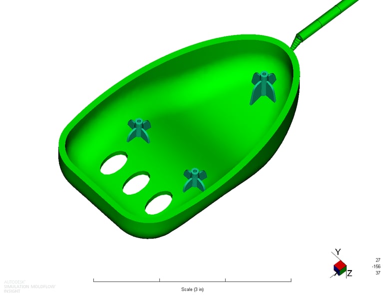 Figure 2: Mouse showing three mounting bosses.
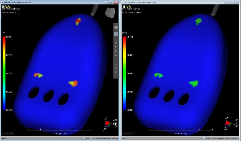
Figure 3: Sink mark plot from Moldflow highlighting the predicted sink mark depth with the original design vs the optimized mouse and boss design.
Determining Feasible Gate Locations
Once a product design has gone through some initial Design for Manufacturing (DFM) analyses, the next design decision for the molder or toolmaker is often how to and where to place the gate to manufacture the part. The gate location and type will dictate the mold construction, parting line decisions, and the need for secondary operations. Additionally, once again the design of the gate is often influenced by the wall thickness of the part where the gate is located.
As a general rule, the following guidelines can be used to help select an appropriate gate location:
- 1. Place the gate to force the material to flow from thick to thin areas of the part. Since injection molding is a pressure-driven process the plastic will take the path of least resistance. That means that as the material starts filling the mold, the molten resin will preferentially flow in the thicker areas of the part since the flow resistance is lower. Placing the gate at the thickest wall section of the part will help minimize any flow hesitation in the thinner areas, which will minimize any material cooling and reduce the pressure to fill the mold. By placing the gate at the thickest wall section of the part, the gate can be made large enough to maintain pressure on the cavity until the molten plastic has solidified. This will reduce the potential for void formation of sink.
- 2. Select a gate that will generate unidirectional filling pattern. The gate is the location in the mold where the material will start to fill in the mold cavity. By selecting a gate location that avoids any changes in flow direction, the polymer molecules and any high aspect ratio fillers, such as glass or carbon fiber, will orient more uniformly. By orienting the molecules and fillers more uniformly, that material will shrink more consistently and develop less stress in the part that should lead to less part warpage. Figure 4
- 3. Place Weld Lines in non-critical locations. Weld lines are areas of a molded part where the molten material flow front split and then rejoin again. At the interface where the flow fronts rejoin, there is often limited molecular entanglement or fiber reinforcement in these areas, which can make them weaker, more brittle regions that have a higher probability of failure. Weld lines are a result of the flow progression in the mold which is often driven by the gate location. Injection molding simulation can help identify the location of these weld lines, and can be compared to a stress distribution plot from a structural FEA to see if the weld lines coincide with high stress or strain areas in the part, Figure 5. By proactively selecting a gate location that avoids placing these weaker areas in critical locations, the part performance should be improved.
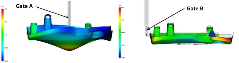
Figure 4: Images showing the predicted part deformation from two different gate locations. Gate B helps produce a unidirectional filling pattern that helps reduce the warpage in the part.
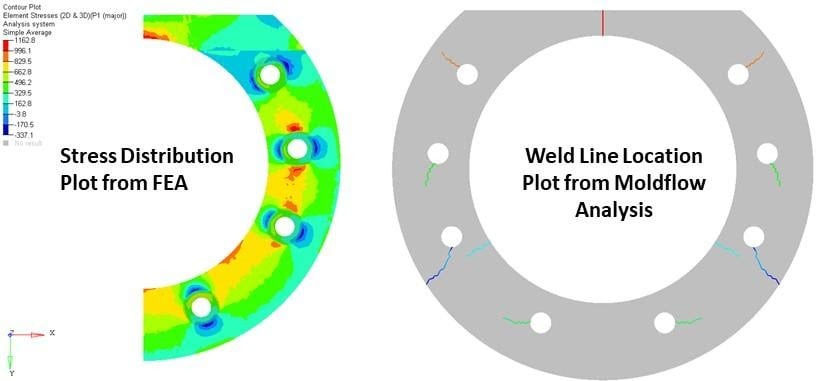
Figure 5: Images showing the predicted weld line locations in a part coinciding with high stress areas, which could adversely affect the part performance.
Selecting a Material
During the design evaluation a great amount of time and effort are placed on selecting the correct resin for an application to help ensure robust part performance and obtaining the desired part aesthetics. However, material selection cannot be decoupled from manufacturing, and often there are several potential material options that can be selected from after the selection process is complete. By utilizing injection molding simulation during the material selection process or at least early in the design phase, the optimal material for both manufacturing and while in service can be selected. By ensuring the material selected is capable of meeting tolerances and part aesthetics prior to having first shots also allows for a wider possible selection of alternative resins where shrinkage can be adjusted in the 3D CAD. By waiting to have first shots, the manufacturer and designer are more restricted to select a resin based on shrinkage value, that is less well suited for service in the field. By integrating injection molding simulation into the material evaluation the correct material can be selected for the application and will avoid having to shoe-horn a material into an application that may result in a sub-optimal part.
Bringing it All Together
The optimization of a plastic part design requires a holistic approach that dictates designers consider the part design, material selection, and manufacturing process collectively. Often in order to find a viable option within each selection area there need to be trade-offs in other areas. By integrating injection molding simulation early on in the design phase any potential risk that could be detrimental to the part performance can be identified prior to any mold construction, and actually help accelerate the mold design process by minimizing any rework.
Copyright (C) 2020 The Madison Group. All rights reserved.
Do you use any of these tips and tricks in your daily workflow? Feel free to brag about your success in the comments!
Like what you’ve read? Subscribe to our blog!
Feel free to share on Twitter or Facebook!