Inventor - Centering a Hole in a Slot with the Joint Command
In this blog post, I’ll tackle a question that came in on our tech support line. The client wanted to mount a motor onto a mounting plate and utilize the Joint command to control the amount of sliding motion available. They were having a little bit of difficulty, so I utilized the following process to supply the controls needed for the motor mounting.
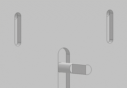
Mounted Motor at the “Top” Range of Slot
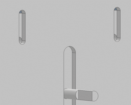
Mounted Motor at the “Bottom” Range of Slot
The Joint command can be a powerful tool for building relationships as it introduces all sorts of flexibility for the desired motion, if motion is desired. The two primary factors in utilizing any type of Joint are selecting the proper connection point and then the desired orientation. If motion is desired, the Joint command also offers options to limit the amount of motion in the relationship. I’ll walk through the steps, graphically, below.
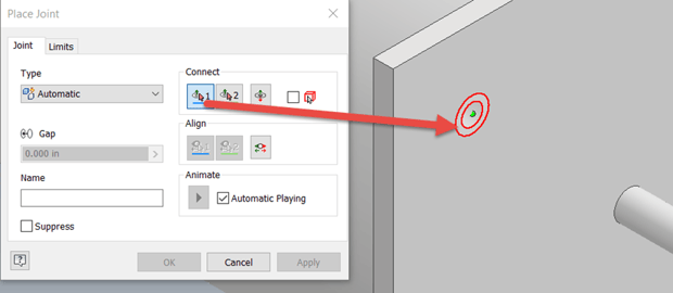
Launch the Joint Command and Select a Hole on the Motor Mount for the First Connection Point
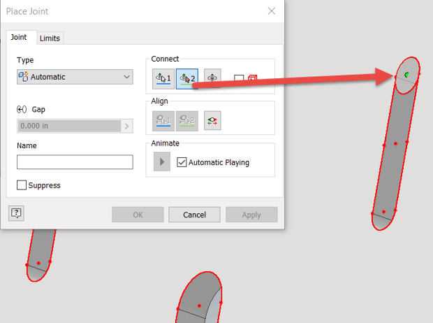
Orbit the Model to the Corresponding Slot to the First Hole Selection and (Optionally) Select the Center Point at Either End of the Slot as the Second Connection Point
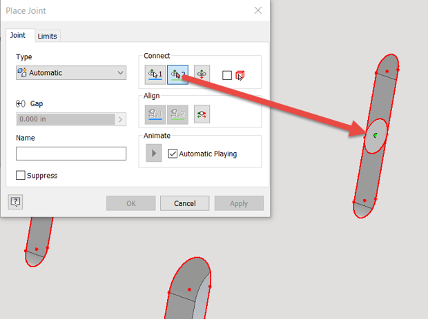
If Desiring to Center the Hole in the Slot, Hold Down the “CTRL” Key on the Keyboard, while Hovering on the Surface Next to the Slot and Move the Mouse to the Point at the Center of the Slot for the Second Connection Point
By utilizing the Center Point of the Slot for the second Selection Point, the motor itself is centered in the mounting plate pattern. Please note that either point for the second Selection Point is valid, as we can still control the component alignment and range of motion from either point. Please see this video link for more information on using the “CTRL” and Hover method for selecting Joint Connection Points.
The Joint may default to the “Rigid” type, which leaves the motor centered in the mounting pattern. If that’s what you’re looking for, then good news, you’re done! However, it’s more realistic to utilize the range of motion in the slot for final adjustments and tensioning any belts or chains, so please read on to see how to control alignment and the range of motion.
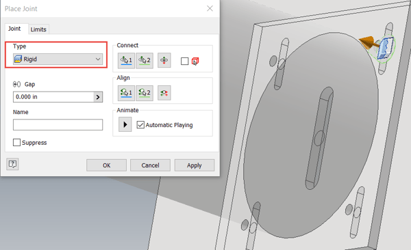
The “Rigid” Type Joint Result Centers the Motor in the Mounting Pattern
When switching to a different Joint type, often the alignment will require adjustment. In this example, we want to use the “Slider” type Joint, but switching to this type causes the motor to slide 90 degrees to the direction of the slot. The green arrow in the preview indicates the direction of the sliding, which is extremely helpful, and the Joint command also animates a preview of the motion. This will quickly reveal BIG issues 😊
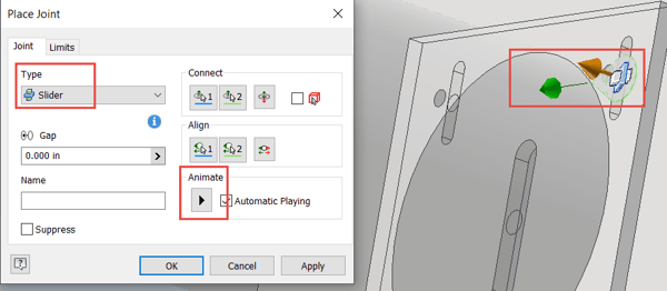
Switching to the “Slider” Type Joint Requires Adjustment to the Alignment of the Joint Command
Making adjustments is typically the most tedious aspect of applying Joints and has the longest learning curve. Please note that you can only reference the two components connected in the Joint when adjusting the alignment. In this case I’m going to choose two edges, the first one from an edge of the motor mount and the second edge from the slot itself, as shown below.
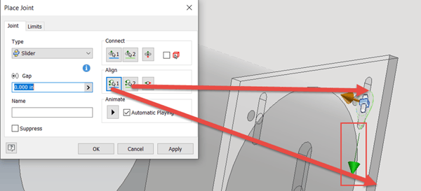
Adjust the Joint Alignment by Choosing the Indicated Edge of the Motor Mount for the First Selection and the Indicated Edge of the Slot itself for the Second Selection, Note the Direction of the Green Arrow
Now that the motor is properly connected and sliding in the correct direction, we must apply limits, otherwise the motor will slide infinitely in either direction. Since the slot in the plate is going to be the limiting factor, we’ll utilize that to control the amount of slide that the motor possesses. This is accomplished using the “Limits” tab of the Joint dialog box. Sometimes, we don’t know the distance for this motion, so we can measure the geometry to obtain the limit values, as shown below.
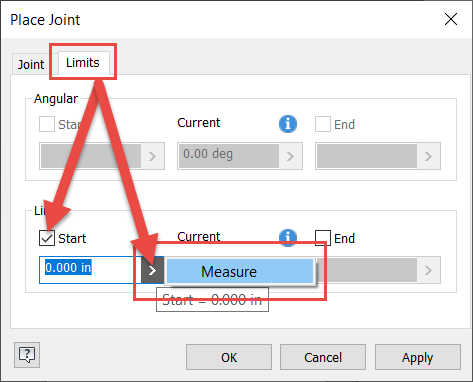
Switch to the “Limits” Tab of the Dialog Box and Select a Start Limit and Utilize the Measure Option
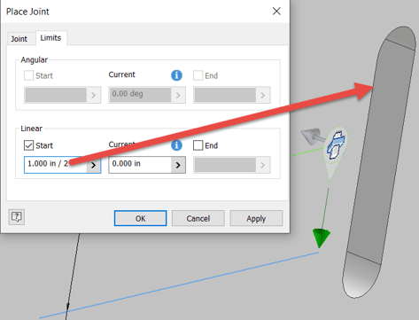
Measure the Edge of the Slot or Between the Two Arc Center Points. Since We’re Using the Center Point of the Slot for the Connection, We Only Want to Use Half the Slot Length for the “Start” Limit
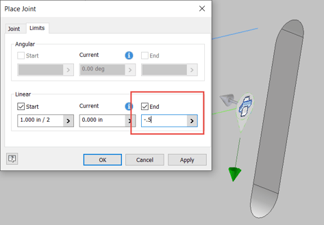
Apply Half the Slot Length to the “End” Limit, Being Sure to Use a Negative Sign at the Front of the Value to Indicate the Opposite Direction Limit, as We’ve Centered the Hole in the Slot
Once you’ve completed the Limits on the Joint command, click OK and test the new relationship. You’ll be able to slide the motor from the top edge of the slot, down to the bottom edge. In a full design the location of the pulleys and sprockets will control the final position of the motor and one can ground the motor once the final position has been determined.
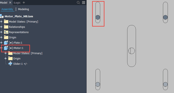
Ground the Motor Once the Final Position has been Determined
So that’s the process! The most challenging portion will be the alignment of the Joint motion, so definitely spend a little bit of time practicing those selections. Hopefully, you found this helpful and please let me know if you have any questions or what posts you’d like to see in the future. Happy blogging and have a most blessed day!
Link to YouTube Video:
Download the PDF file for this post!
Do you use any of these tips and tricks in your daily workflow? Feel free to brag about your success in the comments!
Like what you’ve read? Subscribe to our blog!
Feel free to share on Twitter or Facebook!