Method for Controlling Frame Generator with Model States
In the never-ending quest to find more efficient design methods for our clients, I’ve tried to tackle controlling Frame Generator framing with Model States. Unfortunately, there is no current out-of-the-box method for this, as Frame Generator subassemblies do not possess Model States… However, by incorporating some iLogic, there is a way to mimic the performance of Model State control for these Frame Generator assemblies.
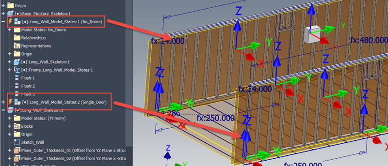
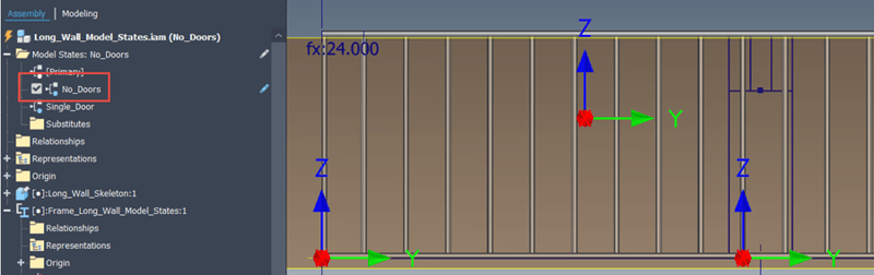 Frame Generator Model with “No_Doors” Top-Level Model State
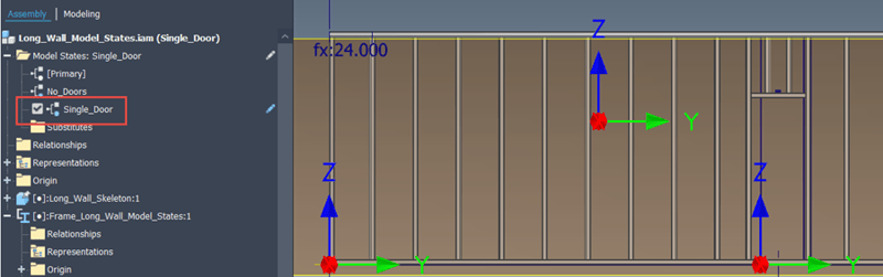 Frame Generator Model with “Single_Door” Top-Level Model State
To achieve this goal, building and naming the Frame Generator members is essential. In order to stay better organized, my skeletal model has different sketches for the framing configurations that I desire, as shown in the image below.
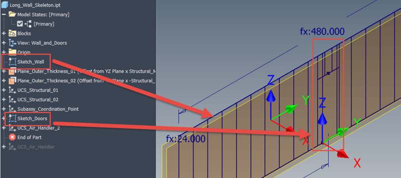 Skeletal Sketch Model with Overall Framing and Door Specific Sketches
When building the frame members, it is important to distinguish the framing that always exists, top, bottom, left and right sides, from the other specific framing. I won’t go into Frame Generator theory, as that’s not the purpose of this post, but I recommend applying primary frame members in one application and then anything specific, like the doors, in a separate application. Also, it is critical, with this method, to name the door framing specifically. In this example, I knocked out the wall framing first, then added the door framing, ensuring the door framing contained the “_Door” portion in the name. If these are not differentiated the iLogic code will not work. Please note that the “Reuse” frame command can save work for the intermediate wall pieces, or a pattern could be applied. If the wall length is dynamic, then a parametric component pattern would be best.
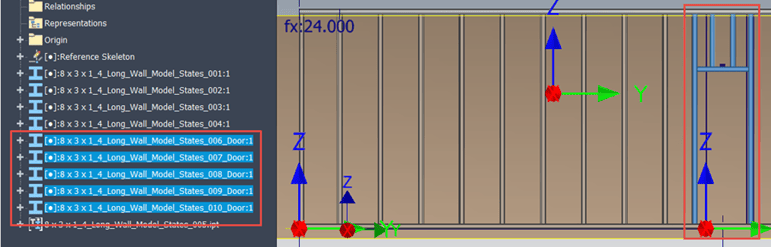 Frame Members Placed with Specific Naming
In order to activate the controls, there must be some top-level assembly Model States to drive the iLogic code. You can use whatever names are appropriate, but please be consistent!
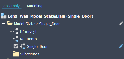 Model States Employed in this Example
Armed with the model state names, iLogic can be employed to determine which frame members are situationally suppressed. The code is available at the end of this post, but here are some highlights of what the code is accomplishing:
- Identify the Frame Assembly in the code
- Create two collections, one containing the door frame members and the other the balance of frame members
- Using the “Analyze Interference” tool, determine which framing interferes with the door framing
- Depending on the active Model State, suppress the unnecessary or interfering framing
In addition to the code itself, I utilized an “Event Trigger” to ensure the iLogic code fires when Model States are activated.
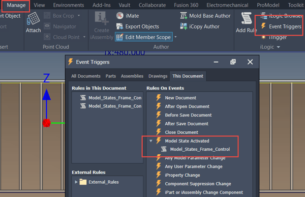 Utilize an Event Trigger to Ensure that the iLogic Rule Runs when Model States are Changed
This provides a great workaround for using Model States to control the Frame Generator. Unfortunately, there is a big limitation with this approach… Because Frame Generator subassemblies do not inherently possess Model States, you would need to create two separate wall assemblies for a “left” and “right” wall, because the Frame Subassembly cannot have two rosters of members suppressed simultaneously. Hopefully, Autodesk will provide a better long-term solution, but this method can work for now.
 Frame Generator Subassemblies Will Only Adjust if Unique Wall Assemblies are Utilized in Upper Level Assemblies
So, this is the current technique, with that limitation. Ideally, Autodesk will add Model States to Frame Subassemblies, which would allow Model State linking to drive further downstream efficiency gains. However, this current method allows Frame Generator control from a top-level assembly, which adds loads of flexibility for modular-type designs. Hopefully you found this tip intriguing and helpful and please leave comments and questions below. Thanks for reading, happy blogging and have a most blessed day!
iLogic Code Sample:
'This rule will allow the model state to control the frame members that are active
'Define the top level variables
Dim oAssembly As AssemblyDocument = ThisDoc.Document
Dim oFrameAssembly As AssemblyDocument
Dim oAssyOcc As ComponentOccurrence
'Find the Frame subassembly
For Each oAssyOcc In oAssembly.ComponentDefinition.Occurrences
If oAssyOcc.Name.Contains("Frame_") Then
oFrameAssembly = oAssyOcc.Definition.Document
End If
Next
'Logger.Info(oFrameAssembly.ComponentDefinition.Document.DisplayName)
'Build collections of Frame member occurrences containing the name door
'and a different one for all other Frame member occurrences
Dim oDoorFramesColl As ObjectCollection
oDoorFramesColl = ThisApplication.TransientObjects.CreateObjectCollection
Dim oFramesColl As ObjectCollection
oFramesColl = ThisApplication.TransientObjects.CreateObjectCollection
'Cycle through all the Frame member occurrences and put them in the proper collection
For Each oAssyOcc In oFrameAssembly.ComponentDefinition.Occurrences
If oAssyOcc.Name.Contains("_Door") Then
oDoorFramesColl.Add(oAssyOcc)'.Definition.Document)
Else
oFramesColl.Add(oAssyOcc)'.Definition.Document)
End If
'Unsuppress any component that currently is suppressed to check the interferences below
oAssyOcc.Unsuppress
Next
'Logger.Info(oDoorFramesColl.Count)
'Logger.Info(oFramesColl.Count)
'Check to see if the frame members are interferring with each other
Dim oInterfResults As InterferenceResults
oInterfResults = oFrameAssembly.ComponentDefinition.AnalyzeInterference(oDoorFramesColl, oFramesColl)
'Logger.Info(oInterfResults.Count)
'Find the names of the interferring occurrences
'Suppress the occurrences, depending on the
Dim oResult As InterferenceResult
For Each oResult In oInterfResults
Logger.Info(oResult.OccurrenceOne.Name & " Conflicts with " & oResult.OccurrenceTwo.Name)
'Suppress the occurrence depending on the active model state
'If the active model state of the overall assembly is "No_Doors", suppress all the door frame members
If oAssembly.ComponentDefinition.ModelStates.ActiveModelState.Name.Contains("No_Doors") Then
'Suppress all Door frame members in the collection
For Each oAssyOcc In oDoorFramesColl
oAssyOcc.Suppress
Next
Else 'Suppress all the frame members that interfere with the door members
If Not oResult.OccurrenceOne.Name.Contains("_Door") Then
oResult.OccurrenceOne.Suppress
End If
If Not oResult.OccurrenceTwo.Name.Contains("_Door") Then
oResult.OccurrenceTwo.Suppress
End If
End If
Next
Link to YouTube Video:
Download the PDF file for this post!
Do you use any of these tips and tricks in your daily workflow? Feel free to brag about your success in the comments!
Like what you’ve read? Subscribe to our blog!
Feel free to share on Twitter or Facebook!