Controlling Bolted Connections by Editing the Excel Hole Tables
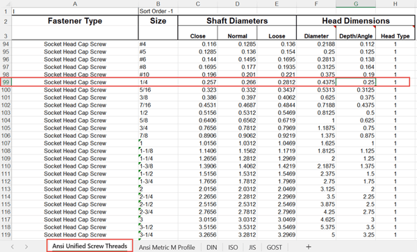
In my last post, we discussed a way to control the settings of holes using the Preset tools. This is an excellent way to standardize hole configurations across a design group but does require each hole to be configured. If there is an entire category of holes to be modified, or if you’d like to introduce a new category of holes, then creating Preset holes could become a bit cumbersome. In that event, it may be easier to modify the Excel tables that Inventor uses to populate the Clearance, Tapped, and Taper-Tapped hole configurations. Below is an example of a Clearance Excel table.
 Adjusted Hole Settings Controlled Via the Hole Preset
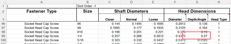
 Out-of-the-Box Hole Configuration Settings Based on the Excel Spreadsheet
Thankfully the process for editing the Excel spreadsheets is pretty straightforward. Here are the steps below:
- 1. Locate the proper Excel spreadsheet.
- 2. Create a backup of the Excel spreadsheet to preserve previous settings.
- 3. Open the Excel spreadsheet and make the necessary edits
- 4. Save and Close the spreadsheet.
- 5. Launch Inventor and test the new settings (must close Inventor if the software is open when the spreadsheet is edited).
To determine the location of the Excel spreadsheets, we need to open the Project tool and identify the file paths for the Design Data. Within the Design Data, we need to navigate to the Design Data\XLS\en-US location and then make a backup copy of the spreadsheet that we’d like to modify. In this example, we’re modifying a clearance hole, so we’ll need to backup and modify the “clearance.xls”. I typically add a date stamp to my backup files, so I have a history of the modifications that I can fall back on. Of course, if one is using Vault, then previous versions will serve the same purpose.
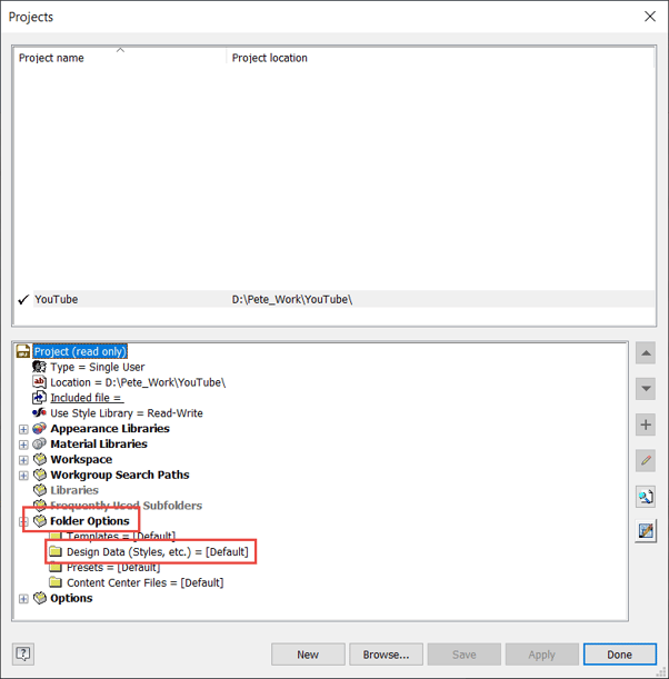 Find the Location of the Hole Spreadsheets in the Folder Options – Design Data
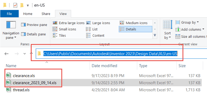 Navigate to the Design Data\XLS\en-US Location and Make a Backup Copy of the “clearance.xls”
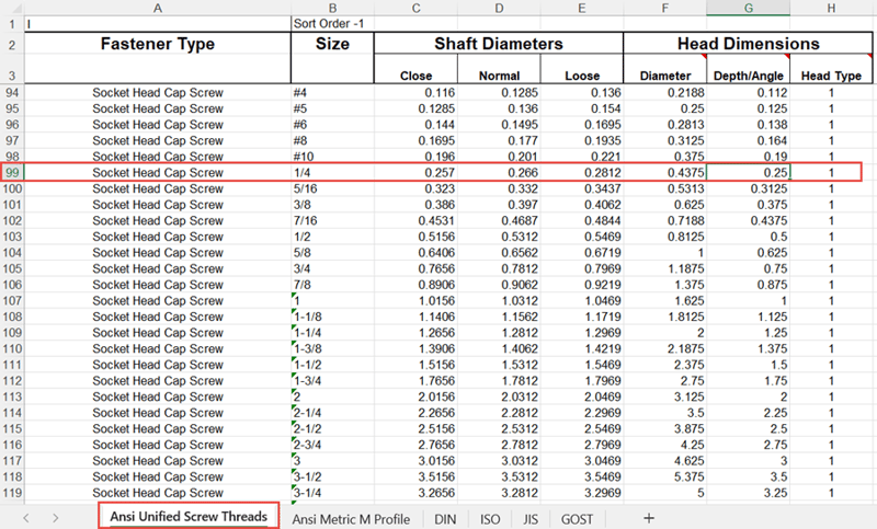
Once inside the spreadsheet, we have to navigate to the appropriate tab. Since we’re using an imperial fastener, a ¼” socket head screw, we will switch to the “Ansi Unified Screw Threads” tab. Inside this particular tab, the clearance holes are differentiated by the different head types: flat head, hex head, oval head, and socket head. In this example, since we’re looking specifically at the socket head, we’ll look in that section and find the ¼” size and the counterbore depth. We’ll adjust that counter bore depth to 0.270” so that the fastener in the bolted connection is recessed further into the plate.
 The Original Value for the Depth of the Counterbore
 Modified Value for the Desired Counterbore Depth
After closing and restarting Inventor, edit the hole feature and cycle to a different value and then back to the ¼” Socket Head Cap Screw. Notice the value has updated to the new spreadsheet value.
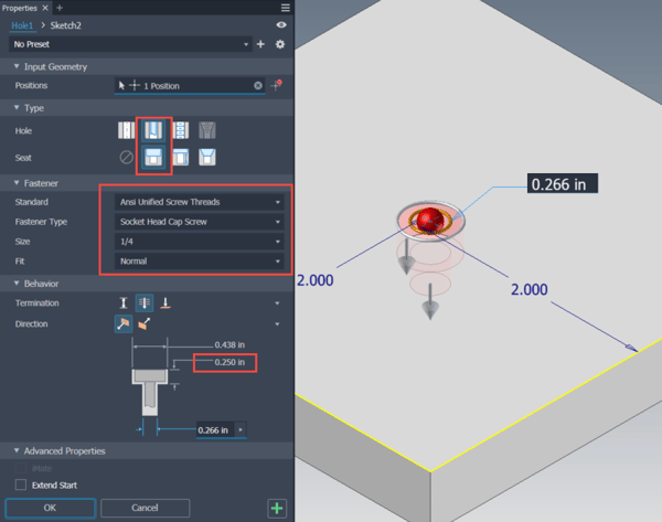 Configuration of Original Hole
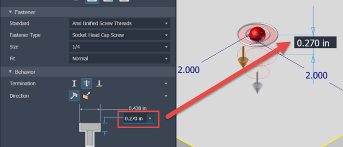 Modified Value when Toggling Away and Back to the Desired Hole
Once the hole has been modified in the part, it is time to adjust the Bolted Connection in the assembly. My STRONG recommendation is to use the “By Hole” option when building Bolted Connections, as this will more easily adjust to changes in the model. In our case, since the Bolted Connection has already been formed, we’ll have to take the extra step of editing the Bolted Connection itself. Fortunately, all one has to do is open the editor and click OK, so no actual changes in the Bolted Connection are required.
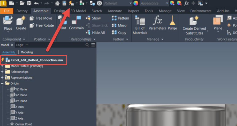 Update the Assembly, if Prompted, to Gather the Latest Component Modifications
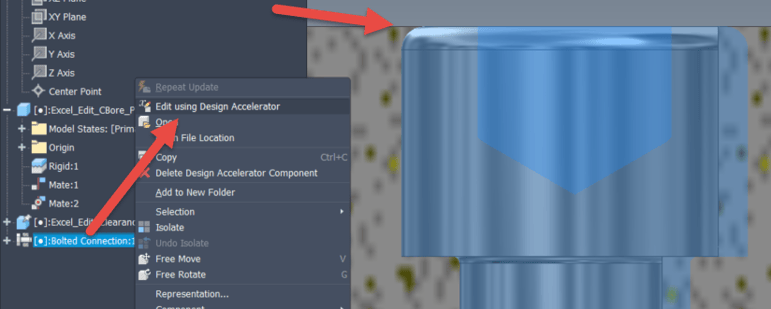 The Bolted Connection Still Requires Editing, Even After the Assembly Update, Right-Click to do so
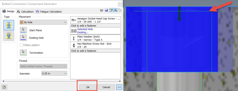 Merely Opening the Editor Repositions the Fastener (Note the Green Line for Top of Fastener) and Just Click OK
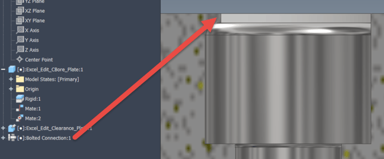 The Bolt is Now Recessed into the Plate
Voila! By modifying the Excel Spreadsheet and utilizing the “By Hole” option in the Bolted Connection tool, one can achieve greater control and consistency across the design group. This technique can also be a great way to create your very own Hole Tabs and control all the holes in one location. Hopefully you found this tip helpful and let us know if you have any comments or questions. Happy Blogging and have a most blessed day!
Link to YouTube Video:
Download the PDF file for this post!
Do you use any of these tips and tricks in your daily workflow? Feel free to brag about your success in the comments!
Like what you’ve read? Subscribe to our blog!
Feel free to share on Twitter or Facebook!