How to Parameterize the Location and Orientation of a UCS
One of my favorite parts of this job is getting to experiment on solving customer problems as efficiently as possible. This can involve using newly emerging technologies, but often it involves taking a step back and reevaluating the tools that we already have. This second approach is the subject of today’s blog post. What if we can take the powerful, and underutilized (in my opinion), UCS tool and make it do more for us? By using UCS’s to allow us to quickly connect components together, we could save tons of time building assemblies. The UCS would be even more powerful in that capacity, if I can parametrically control its location and orientation… Thankfully, I can! Please follow along, friends, as we commence this mystical journey into the world of parametric UCS’s!
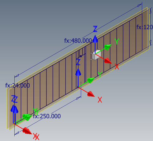
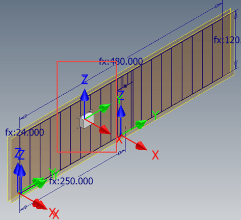
Original Position of Component Based on UCS Constraints
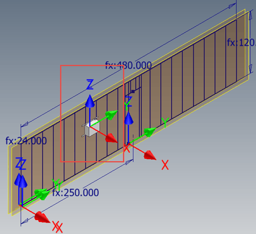
Component Repositioned after UCS Adjusted Parametrically
First things first, we need to establish a new UCS. This is very straightforward and to utilize the parameters more easily, simply locate UCS at the Origin – Center Point and then right-click to Finish, which forces the UCS to take on the same orientation as the Origin – Axis. Rename the UCS to help identify the type of connection / component that can be made in the assembly, as well as set the stage for future automation of constraints.
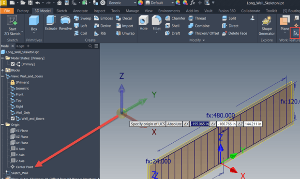
When Creating the UCS, Use the Origin – Center Point for the Origin and the Origin – Axis for the Orientation
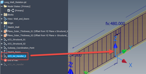
Rename the UCS that is Now Located on and Oriented about the Origin Geometry
Now that the UCS is in place, we can utilize Inventor parameters to control its location. This can be particularly helpful for constraining downstream assembly components that can be dynamically located. Using a mix of User Parameters and Equations / Functions, both the Translation and Orientation of the UCS can be controlled via the Parameter Table. In my experience, using the Parameter Table is the most reliable and easy method for adding parametric controls. Depending on where the original point was located, be aware that you may have to use negative “-“ values or implement equations to get the desired result. For example, since my wall section is centered, if I wish to locate a UCS from one end of the design, I’ll have to work with the Length_OA of the wall divided by 2.
IMPORTANT NOTE: When viewing the UCS Model Parameters in the Parameter Table, the topmost value is “X”, 2nd is “Y”, and the bottommost value is “Z” for both the Translation and Rotation Values.
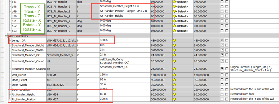
Parameter Table with Equations and Values Controlling the UCS
With UCS parametrically controlled, we can now employ its use in the assembly to quickly constrain the air handler to the wall. To accomplish this task, we’ll work with the uncommonly applied Constraint-Set constraint. Please note this will only work if the corresponding component also possesses a UCS in the proper location and orientation.
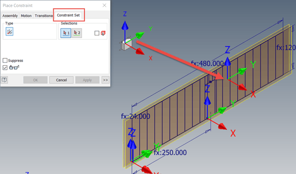
Utilize the Constraint-Set Constraint to Relate the Air Handler UCS to Wall UCS
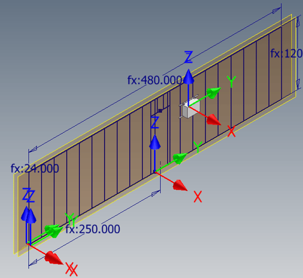
Result of the Constraint Set
To simulate a design change, return to the Wall Skeletal model and change the parameter value for Air_Handler_Position and note the results in the assembly.
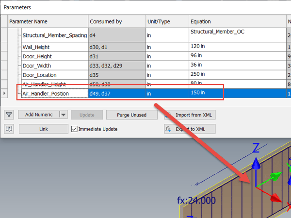
Changing Wall Skeleton Parameters Repositions the UCS
Updating the Assembly File Repositions the Constrained Air Handler
So, there you have it! A parametric UCS can be extremely helpful for dynamically positioning components in an assembly. The overall workflow is still a bit experimental, as there are some issues I’m working through with component replacement, but I’m finding the overall approach more efficient than building and combining composite iMates… Hopefully you find this tip intriguing and helpful. Please share any comments or questions below, happy blogging and have a most blessed day!
Link to YouTube Video:
Download the PDF file for this post!
Do you use any of these tips and tricks in your daily workflow? Feel free to brag about your success in the comments!
Like what you’ve read? Subscribe to our blog!
Feel free to share on Twitter or Facebook!