Inventor Tips & Tricks – Create Contour Flanges from Contour Rolls
Inventor contains excellent tools for modeling Sheet Metal components and the “Contour Flange” is my all-time favorite. I use that tool ALL the time when I’m modeling sheet metal parts, as it is crazy flexible and can create almost any shape that I can think of, including today’s scenario, modeling a Contour Flange from the end of a Contour Roll.
A client recently reached out and was having difficulty figuring out how to get the Contour Flange modeled as shown below. While one could extrude from the end of the Contour Roll, there is a way to model this feature using a Contour Flange. Please settle in as we go on a mini sheet metal adventure together! Fear not, it’ll be a pretty short adventure…
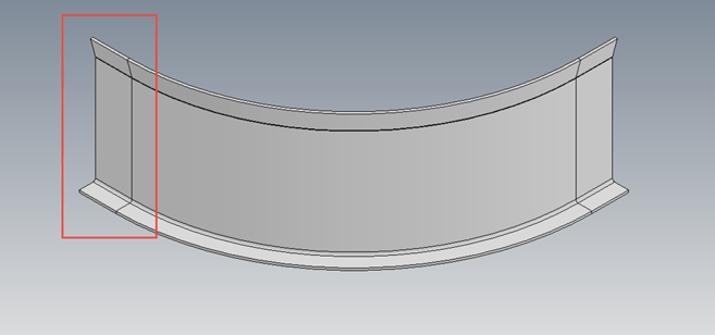 The Final Objective: A Contour Flange from the End of a Contour Roll
The first step is to create a sketch at the end surface of the Contour Roll feature. Project the entire connected edge of one side of the feature. I typically utilize the outer edges, meaning the edges opposite the bend radius (inner) edges, see the image below. Finish the sketch once all the desired edges have been projected.
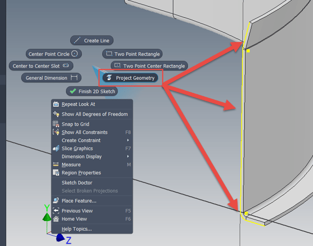 Project All the Outside Edges on a Sketch at the End of the Contour Roll
Launch the “Contour Flange” command and select the newly projected edges as the “Profile”. Not much will happen and don’t be alarmed, as the Contour Flange defaults to “Edge” mode when there is a preexisting sheet metal feature. Simple switch the “Width Extents” Type to “Distance” and you will be well on your way. Double check the shape is thickening correctly and key in the desired length for the flange.
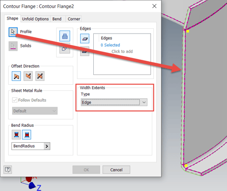 Select the Projected Sketch Geometry in the Contour Flange Tool
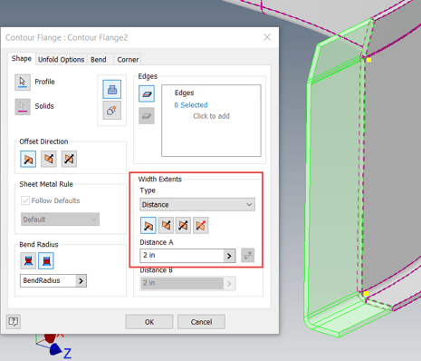 Switch the Width Extents Type to Distance and You’ve Won the Day
Boom! You’re done! Nothing to it, once you remember to toggle the Width Extents. Hopefully you find this tip helpful and please let us know if you have any questions or comments. Happy blogging and have a most blessed day!
Link to YouTube Video:
Download the PDF file for this post!
Do you use any of these tips and tricks in your daily workflow? Feel free to brag about your success in the comments!
Like what you’ve read? Subscribe to our blog!
Feel free to share on Twitter or Facebook!