Inventor Tips and Tricks – Using Equation Curves for Complex 3D Machining Operations
One of the most exciting parts of my job is getting to meet really fun people who work on equally fun and interesting projects.
After one of my advanced Inventor training classes a student came up to me inquiring on how to model a particularly unusual part. It is a little difficult to describe, but essentially a tube has ends cut by a laser and as the tube is getting cut, it is fed into the cutting head and rotated 360 degrees.
Once the tube has rotated 180 degrees, the tube is retracted from the head over the final 180 degrees. Like I said, it is difficult to describe, so I have included the image below to illustrate the motion of the tube.
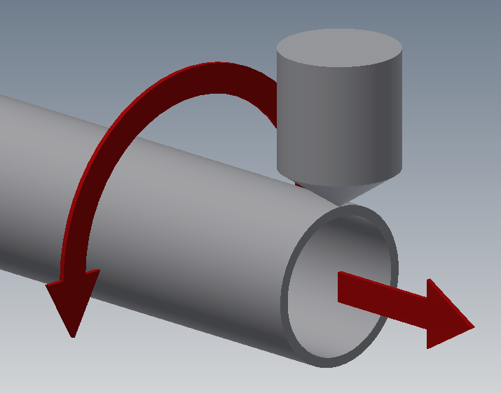
Depiction of Machining Process
There are a couple of ways that this part could be completed, either by approximating the path using intersecting work planes and points or using Equation Curves - which required some knowledge of 3D sketching. Since Equation Curves aren’t a tool that is used too often, I wanted to take this opportunity to illustrate how this tool solved this design challenge perfectly.
One thing that can be very useful when confronted with a difficult design problem is to take a step back and simply try to think through and visualize what the solution should look like. In this case, I would expect a tear drop shape to represent the machining at the end of the tube. See the Images below of the expected result (for the record, I am cheating and showing you the final curves to help illustrate the desired result).
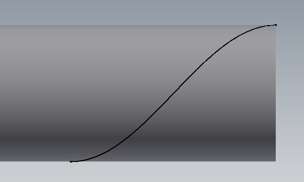
Side View of Desired Cut
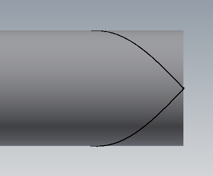
Top View of Desired Cut
As you can see by the Side View, this cut doesn’t seem like that big of a deal and indeed that is how my student had initially started to model the part. However, the challenge comes when one looks at the Top View.
There just isn’t a great way to model that using standard “run-of-the-mill” tools in Inventor. Although one could use a series of work planes and work points, to trace a spline path, this would be a manually intensive and time-consuming process. However, this is a perfect scenario for using a little-known tool called Equation Curves.
Equation Curves are a tool that is utilized in the 3D Sketch Environment. If one is unfamiliar with the 3D Sketch Environment, get ready, this can be a very interesting place. However, once one gets familiar with 3D sketching there are some powerful tools for creating complex geometry. To launch the Equation Curves tool, simply click on Equation Curve Tool, as shown below. I also strongly suggest that you look at the “tool tips” to get a feel for what types of input are required.
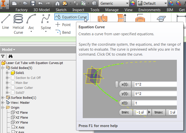
Location of the Equation Curves Tool in the 3D Sketch Environment
The Equation Curves tool allows the user to create equations using three different coordinate systems: Cartesian (X, Y coordinates), Cylindrical (Radius, Length and Angle) and Spherical (Radius, Azimuthal Angle, and Polar Angle); all based on time. The desired curve shape will dictate which coordinate system is used. In this case, cylindrical coordinates make the most sense for our tubular cut. For this operation, I am assuming that the tube will rotate 180 degrees and move 3 inches in 3 seconds. This is reflected in the equations below.
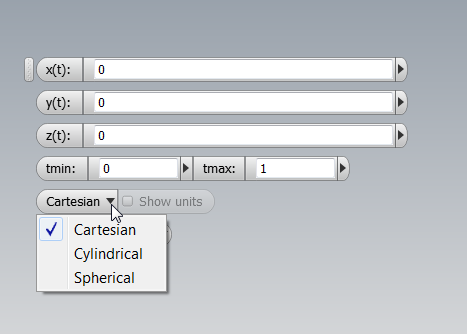
Depiction of Generic Equation Curves Tool
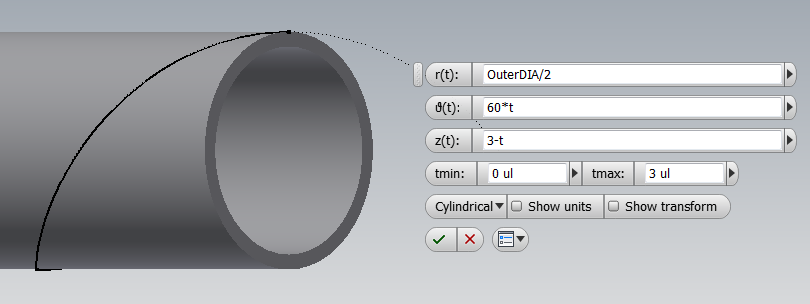
Equations Governing Half of Desired Machining Operation
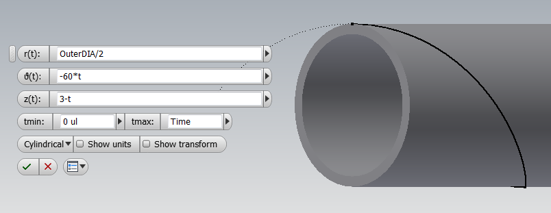
Equations Governing Opposite Half of Desired Machining Operation (Note Angle is Negative)
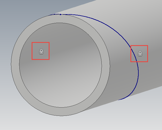
Constraining the Curves After Creating Them is Good Practice (
I Used the Fix Constraints on the Curves Themselves)
Once the Equation Curves are created and constrained, I can use the Boundary Patch tool to create a surface bounded by the two Equation Curves.
Using this Boundary Patch, I can utilize the Split tool to break my part into two different solids and then I can simply turn off the machined solid to get the desired finished tube part.

Boundary Patch of Equation Curves

Resulting Tube with Machined End Removed after Split Tool
Hopefully, you can see how the Equation Curves tool allows us to create some complex geometry in a matter of minutes versus having to create a large amount of work geometry. This is not a tool that you will use all the time, but it is extremely powerful in the right situation. Happy blogging and have a most blessed day!
If you’d like to download a copy of the file, please click on the image link below. - Pete Strycharske
Do you use any of these tips and tricks in your daily workflow? Feel free to brag about your success in the comments!
Like what you’ve read? Subscribe to our blog!
Feel free to share on Twitter or Facebook!