I had a customer recently ask me how to create a cylinder with an angle cut, that could be flattened with the Inventor Sheet Metal tools. Since this scenario is general enough, I wanted to share the most straight-forward solution with all of you, my dear readers! Thankfully, this design scenario is pretty easy to execute and can be accomplished exclusively using Sheet Metal features. For a better understanding of the desired outcome, please see the image below.
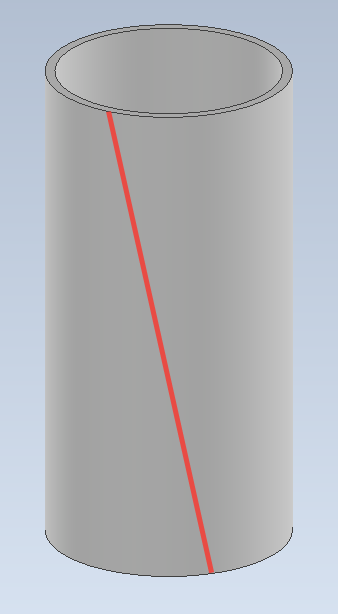
Desired Solution is a Sheet Metal Cylinder with an Angle Cut
I am going to break the solution down into 2 parts: the creation of the closed cylinder first and the angle cut second. To help make this design as flexible as possible, perhaps even as a template design for future use, we will begin by creating some User Parameters. Launch the Parameter Table and create equivalent parameters as shown below.
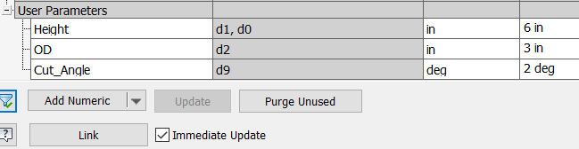
Create User Parameters to Drive the Design
To model the cylinder, by completely using Sheet Metal tools, create a couple of work planes offset by “Height / 2” from one of the origin planes, then create the desired circle shape on a sketch based on one of the work planes. Draw a second sketch on the other work plane and simply project the first circle onto this new sketch. Finally, utilize a “Lofted Flange” feature to create the smooth cylinder with the proper thickness.
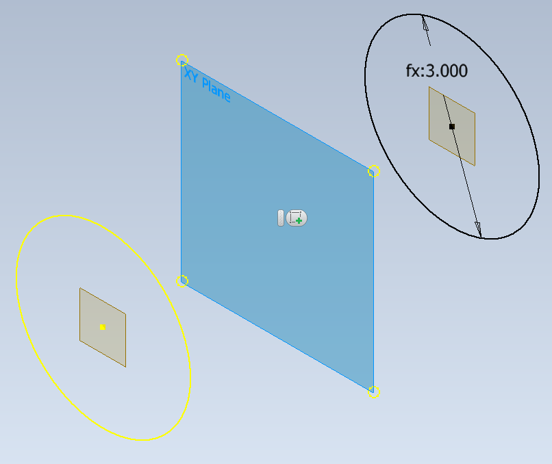
Create Offset Work Planes Symmetrically About the Origin Plane. Then Create Circular Sketches on Each
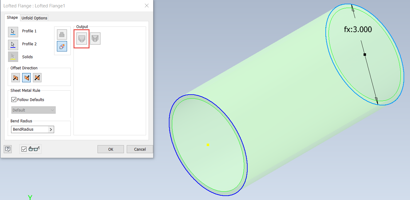
Use the Lofted Flange Tool, with the Die Formed Option, to Create the Smooth Cylinder
Now that the cylinder has been modeled, we can now move on to the angular cut to allow the cylinder to be flattened. Since we modeled the cylinder about the origin geometry, the origin planes can be used as the basis for controlling the cut shape. For the angled cut, create a work plane that uses one of the work planes, rotated about the origin axis that is normal to that plane. Utilize the “Cut_Angle” parameter to determine the angular orientation of the work plane.
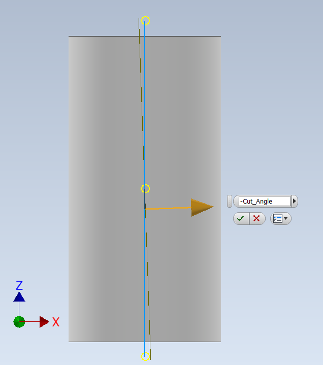
Create a Work Plane Based on the YZ-Origin Plane, that is Rotated About the Y-Axis, Using the “Cut_Angle” Parameter
To define the path of the cut, create some Work Points that intersect the rotated work plane and the top and bottom circular edge of the cylinder. Once the work points have been created, utilize the “Rip” Sheet Metal tool, with the “Point to Point” option to create the desired cut on the exterior surface of the cylinder. Finally create a “Flat Pattern” to see the results.
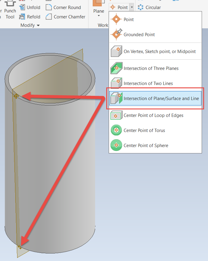
Create Work Points to Start and Terminate the Rip Tool
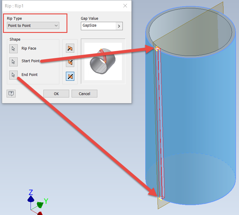
Configure the Rip Command to Use Both Work Points and the Outer Cylindrical Surface
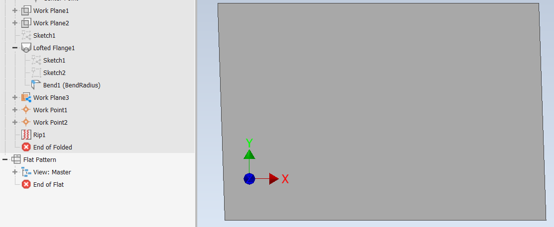
Resulting Flat Pattern
So, there you have it; a way to create and flatten a sheet metal cylinder exclusively using tools found on the Sheet Metal tab of the interface. Additionally, by making the part fully parametric, we can adjust the “Height”, “OD” or the “Cut_Angle“ parameters to modify this and future designs in any way that we need. Please share your questions or comments below and I will be happy to take look. Hope this helps, happy blogging and have a most blessed day! - Pete Strycharske
Do you use any of these tips and tricks in your daily workflow? Feel free to brag about your success in the comments!
Like what you’ve read? Subscribe to our blog!
Feel free to share on Twitter or Facebook!