Manipulating a 3rd Party Assembly: Part 2
Er, Manipulating a 3rd Party Assembly (as a Part)
In my last post, we walked through the process of converting a STEP assembly into an Inventor part. This consolidates the assembly into a format that can be more easily manipulated, which is the focus of this week’s blog.
Picking up where we left off, we’ll simplify the new part and add some basic parametric functionality utilizing a powerful editing tool inside of Inventor.
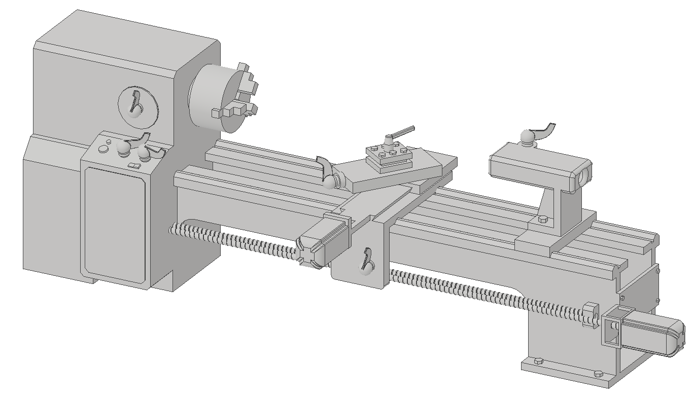
The Converted Assembly as an Inventor Part
In this tutorial, the goal is to change the length of the Lathe bed to accommodate a variety of part sizes, so we should be on the lookout for aspects of the model that will hurt that effort.
After investigating the model, the grooves in the ball screw could cause some problems, as the helical features are not available to manipulate. When we add the parametric capabilities to the model, it will be more difficult, and time consuming, to try and utilize the helical features.

Threaded Rods for Ball Screw May be Problematic Features to Parameterize
To best enhance the long-term performance of this model, we should replace this helical solid with a simpler shape.
These solids could easily be replaced with a simple cylinder and / or a threaded feature, which in Inventor is bitmap representation of the threads. We’ll do this later, for now, simply delete the solid bodies, as adding them later will be more advantageous.

Remove the Ball Screw Solids
Now that the problematic features have been dealt with, we can move on to parametric designs on the part.
Since this is a 3rd party model, we don’t have access to the original features, but Inventor contains a powerful tool that affords us the opportunity to edit these non-native solids; the Direct Edit tool.
The Direct Edit tool allows users to move, resize, delete geometry within the non-native components. This can range from manipulating simple features to repositioning entire solids. To change the size of the lathe bed, we’ll have to do a little bit of both, as some of the changes will involve resizing a solid, the framing of the bed, and moving a solid, the motor assembly. Also, to properly control the changes, we should create some user parameters.
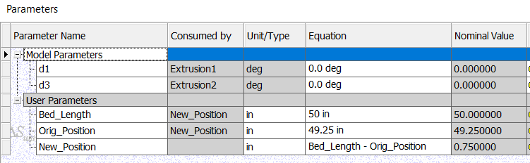
Required User Parameters
The parameter Bed_Length will be used to control the new size of the Lathe bed, Orig_Position is used to capture the initial condition of the Lathe and the New_Position will locate the new solid bodies that have to move with the changes in the Lathe bed size (and will serve another purpose, which we’ll explore next week).
To obtain the Orig_Position value, we’ll use the measure command to obtain the length of the Lathe bed in the current state. The location of the measurement will also be used momentarily to drive the Direct Edit feature.
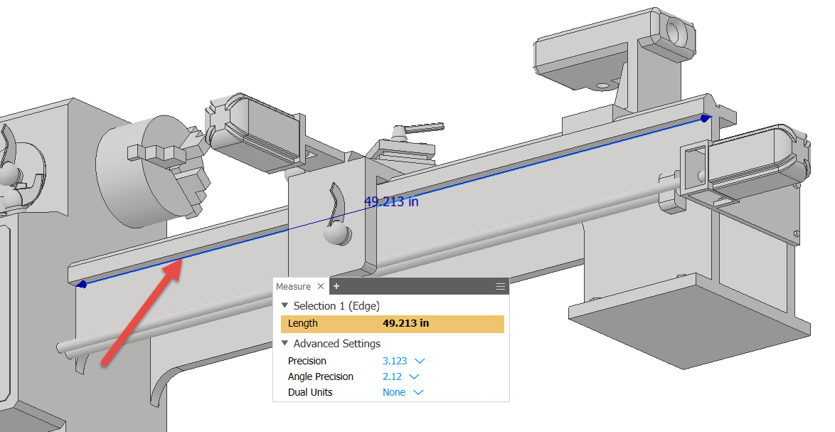
Value and Location of the Original Measurement
(I’ve Rounded the Parameter to 49.25 for Ease and Future Use)
Armed with the length of the Lathe bed, which we add to the Orig_Position, we’ll now use the same location to drive the Direct Edit tool. The Move option within the Direct Edit will be used for the first stage of lengthening the Lathe bed. Please see the images below for the settings and selections for this operation.
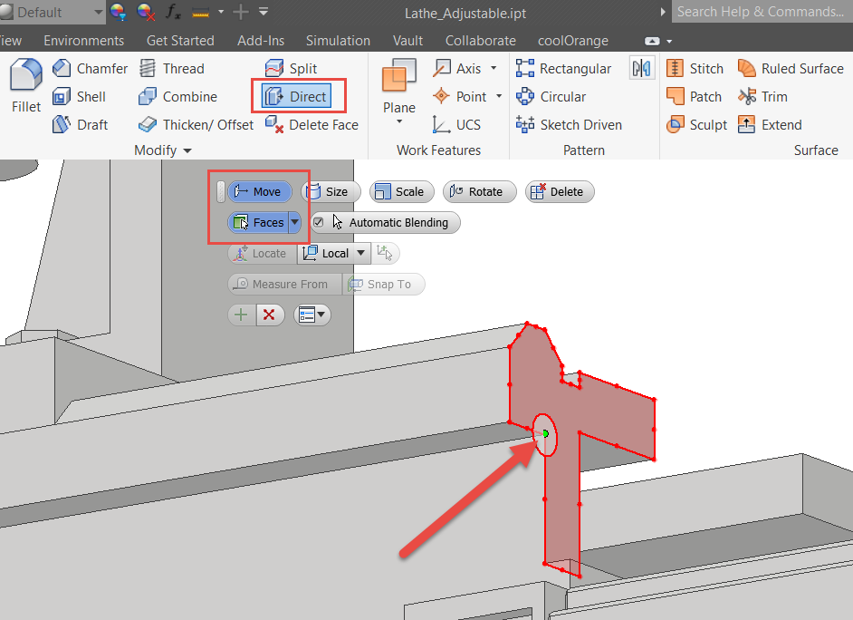
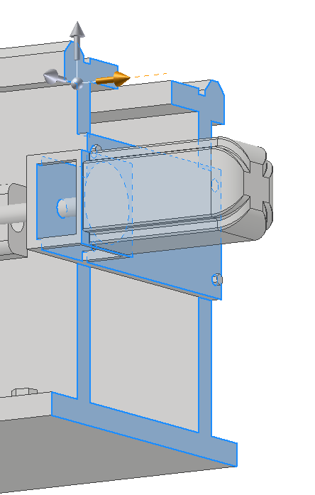
Utilize the Move and Faces Options in the Direct Edit Tool. Select this Point as the Location Point for the Move
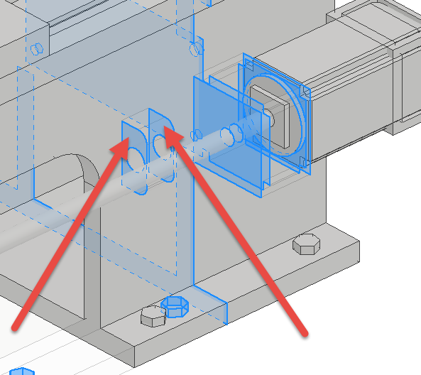
Select all the Outer Surfaces of the Lathe Bed for the Move

Inner Selections of the Lathe Bed (Fillets as well)
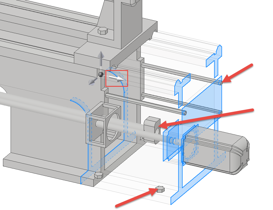
Do a Drag Test Using the Arrowhead (in the box) and Note the Hex Head Bolts and Block
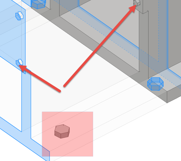
Select Each Bolt Face (as shown) to Include These in the Move
Select Both Sides of the Block to Include in the Move
The test dragging is critical, especially when just getting started with the Direct Edit tool or if there is a lot of geometry to manage. Also, if you missed something and must perform some edits, you can always edit the Direct Edit feature by double clicking on the Move option (as shown below) to alter the selection set.

When Editing the Direct Edit Feature, Double Left-Click the Move Option (in the box) and Add Any Remaining Faces

When Controlling the Movement, Use the Measure from Option to Setup a Specific Distance. Also, Click in the Distance Field, List Parameters and Set the Value to Bed_Length
By selecting the geometry shown above, measuring from the surface at one end of the machine and setting the distance to the Bed_Length parameter; we can now change the length of the bed at will. At this point, though, do not set the Bed_Length equal to the Orig_Position parameter.
(*That may throw an error, which we’ll cover with the next post.
Next, we’ll repeat the same process, but will move the solids, as you may have noticed the motor, guide block and other objects did not move with the Face changes. When we work with the Direct Edit tool this time, we’ll use the Move option, but utilize Solids instead of Faces.
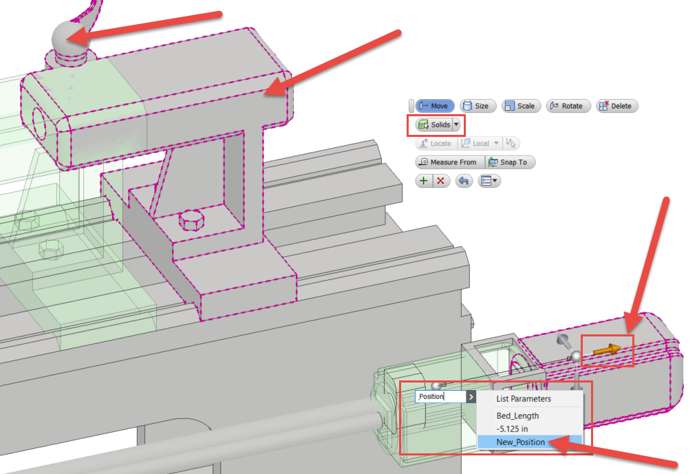
Use the Direct Edit Tool, with the Solids Option and Move the Indicated Solid Bodies. Utilize the New_Position Parameter to Reposition the Solids
The final touch will be to add in the simple cylinders to replace the Ball Screws that we deleted earlier. The reason that we waited until now to add these shapes is, so they’ll adapt to changes in the length of the Lathe Bed.
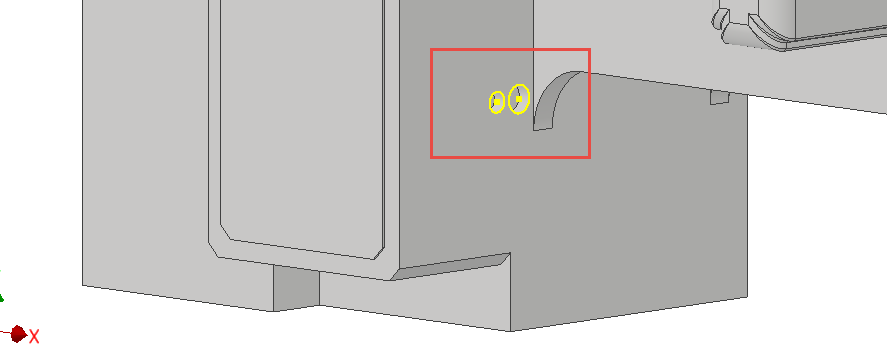
Create a Sketch on the Interior Plane of the Lathe Body and Project the Circles, as Shown
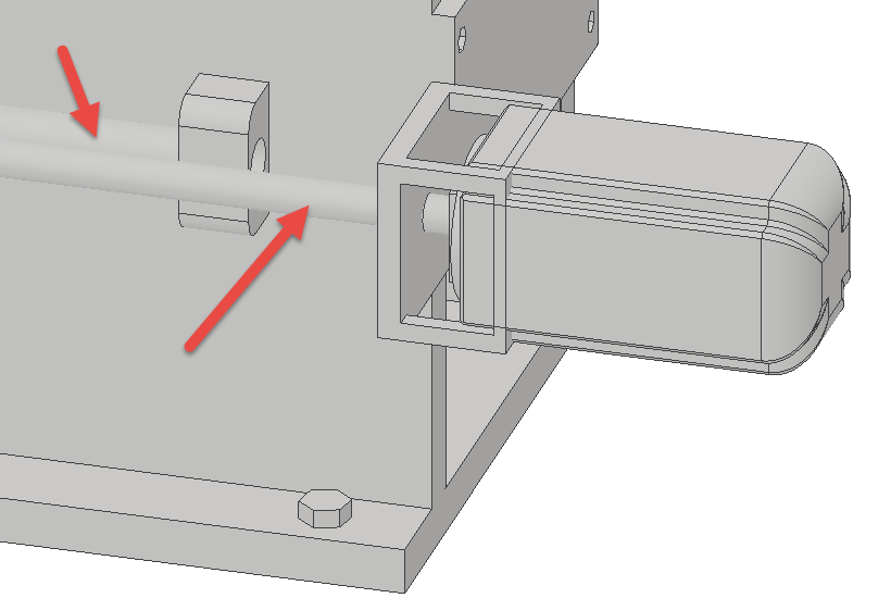
Extrude the Circles to the Block and the Motor and Join to the Lathe Body Solid
Now that the model has been modified and configured to use the parameters of Bed_Length and New_Position, try experimenting with different values for Bed_Length, as shown below, to ensure the model is adapting as desired.

Model Configuration with Bed_Length set to 72 inches

Model Configuration with Bed_Length set to 48 inches
Altering the Bed_Length parameter is adjusting the model as desired and there doesn’t appear to be any problems. However, there is one condition that can sometimes cause problems, when the New_Position equals 0. There are times when modeling in CAD that assigning values of 0 can throw a wrench into things.
While this model is working fine when New_Position equals 0, in the next post I’ll demonstrate a couple of techniques for conditionally suppressing features so that problematic math can be avoided.
We covered a lot of ground in this post, so please post any questions or comments below and I’d be happy to address them. Thanks for reading, happy blogging and have a most blessed day! - Pete Strycharske
Do you use any of these tips and tricks in your daily workflow? Feel free to brag about your success in the comments!
Like what you’ve read? Subscribe to our blog!
Feel free to share on Twitter or Facebook!